
p id symbol for mill manufacturer Grasping strong production capability, advanced research strength and excellent service, Shanghai p id symbol for mill supplier create the value and bring values to all of customers.
 WhatsApp)
Using PID Plant Facilities Symbols to Design PID. Below are some samples illustrating the usage and application of PID plant facilities symbols. Edraw predefined PID symbols provides a fast and easy way to design piping and instrumentation diagrams. To discover more examples, you can visit PID examples and PFD examples.
Sep 28, 2017· PID and PFD Drawing Symbols and Legend list 1. PID/PEFS PFD/PFS Symbols 2. In this video, you will learn Symbols used in Process Flow Diagram (PFD) or Process Flow Scheme (PFS) Piping Instrument Diagram (PID) or Process Flow Engineering Scheme (PEFS) Process Instrument Diagram Visit Today
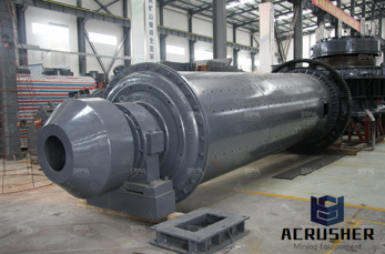
APPENDIX A GRAPHICAL SYMBOLS FOR PIPING SYSTEMS AND PLANT A 7. Solids Handling ... Breaker gyratory Roll crusher Pulverizer : ball mill Mixing (basic symbol) Kneader Ribbon blender Double cone blender Filter (basic symbol, simple batch) Filter press (basic symbol) Rotary filter, film drier or flaker A 8 APPENDIX A GRAPHICAL SYMBOLS FOR PIPING ...
The objective of this Pulp and Paper Energy Best Practice Guidebook is to provide resources and methods to drive down energy use and energy related costs in pulp and paper mills. Using this guidebook, a mill manager will be able to benchmark his or her facility against a comparable low energy using facility and significantly reduce energy
Jul 03, 2012· Piping and Instrumentation Diagram (PID) The piping and instrumentation diagram (PID), also known as mechanical flow diagram (MFD), provides information needed by engineers to begin planning for the construction of the plant. The PID includes every mechanical aspect of the plant except the information given in Table
Like other specialized diagrams, PID''s are comprised of standard shapes and symbols. There''s a huge variety of symbols, depending on industry and manufacturer, so we''ve created this guide to feature the most popular PID symbols supported within our PID software and is standardized for best practice across the industry.
PIDs should show sufficient information to define the process without crowding. One to three pieces of equipment with auxiliaries is normally sufficient for one PID. PID diagrams do not usually use colors to indicate or convey their meaning. Colors are used at the design level in a monitor but are usually printed in black and white.
Aug 12, 2017· Design hub How to read pipe and instrument drawings. Pid is really so complicated and confusable, this video help for all engineering students and professional s for reading pid .
REBAR MILL SYMBOLS. BULL 15 CODE . COMPANY. ... NJ P GERD13 Gerdau AmeriSteel St. Paul, MN U GERD15 Gerdau AmeriSteel Sand Springs, OK O GERD16 Gerdau AmeriSteel Midlothian, TX M GERD17 Gerdau AmeriSteel Vidor (Beaumont), TX B KEYSW Keystone Steel .
A process flow diagram (PFD) is a diagram used in chemical and process engineering to indicate the general flow of plant processes and equipment. Chemical and Process Engineering Solution from the Industrial Engineering Area of ConceptDraw Solution Park is a unique tool which contains variety of ...

surface of one side of the bar to denote the producer''s mill designation, bar size, type of steel, and, for Grade 420 (Grade 60), a grade mark indicating yield strength, and for Grade 520 ... IDENTIFICATION GUIDE FOR REINFORCEMENT STEEL DOWEL BAR PRODUCERS ...
The PID symbol library in AutoCAD electrical includes equipment, tanks, nozzles, pumps, fittings, valves, actuators, logic functions, instrumentation, flow, and flow arrows. The PID symbol library consists of all the piping and instrumentation symbols. ... Select to place the ball mill in the upper left corner of your drawing.
A piping and instrumentation diagram (PID) is defined by the Institute of Instrumentation and Control as follows: A diagram which shows the interconnection of process equipment and the instrumentation used to control the process. In the process industry, a standard set of symbols is used to prepare drawings
The free IAN symbol libraries is a global symbol language containing 2953 environmental science vector symbols and icons in SVG, Illustrator (AI) and PNG (raster) formats.
Title: PID and PFD drawing symbols and legend list Author: HardHat Engineer Subject: PID and PFD drawing symbols and legend list Keywords: pid symbols list; pid; symbols; piping and instrumentation diagram symbols; pid symbols for valves; pid symbols standards; pid symbols dwg; pid symbols chart; pid symbols legend; pid symbols library; pid symbols oil and gas; pid .
Standard PID Symbols Legend | Industry Standardized PID Symbols Piping and Instrument Diagram Standard Symbols Detailed Documentation provides a standard set of shapes symbols for documenting PID and PFD, including standard shapes of instrument, valves, pump, heating exchanges, mixers, crushers, vessels, compressors, filters, motors and ...
Insert PID components from the icon menu. The PID symbol library in AutoCAD electrical includes equipment, tanks, nozzles, pumps, fittings, valves, actuators, logic functions, instrumentation, flow, and flow arrows. The PID symbol library consists of all the piping and instrumentation symbols. It is found at UsersPublicDocumentsAutodeskAcade {version}LibsPid.
PIDs can seem mysterious, but don''t have to stay that way thanks to our intuitive PID software. Learn the what, why, and how of everything Piping Instrumentation Diagrams in this comprehensive guide. 12 min read Want to make a PID of your own? Try Lucidchart. It''s quick, easy, and completely ...
p amp id symbols hammer mill p id symbol for hammer mill . hammer mill p id symbols dwg . Crushing And Mining is a leading and pioneering enterprise with the most advancedinternational level in RD, manufacturing and selling of largescale crushing. Contact Supplier . .
Standard PID Symbol Legend | Industry Standardized PID Symbols. Piping and Instrumentation Diagram Standard Symbols Detailed Documentation provides a standard set of shapes symbols for documenting PID and PFD, including standard shapes for instrument, valves, pump, heating exchanges, mixers, crushers, vessels, compressors, filters, motors and connecting shapes.
PID symbols exist for all major components and lines, such as valves, vessels, instruments, pumps, compressors, and towers. The ISA, ISO 10628, and BS 5070 cover the standardization of PID symbols and guide process engineers in their plant design activities. The most common PID symbols are listed below: lines
p amp id symbols hammer mill p id symbol for hammer mill hammer mill p id symbols dwg crushing and mining is a leading and pioneering enterprise with the most advancedinternational level in rd manufacturing and selling of largescale crushing contact supplier free quote leave your needs.
The symbols used in piping and Instrumentation diagrams or drawings are many and varied. I have dealt with some of these symbols before but here I have given a comprehensive list of the common PID symbols of process equipment such as valves, flowmeters, piping line connections, and much more.
ISA Instrumentation Codes in Process Control Systems The ISA standards and symbols are important for the PIDs and documents describing the process control system; PID Diagram Online Drawing Tool Draw PID diagrams online in the browser with Google Docs
WhatsApp)